


01 Source
Start with the laser you have.
Set a collimated flat-top or Gaussian beam, its diameter, and its wavelengths. This one is a 4 mm flat-top beam at 1.064 µm.
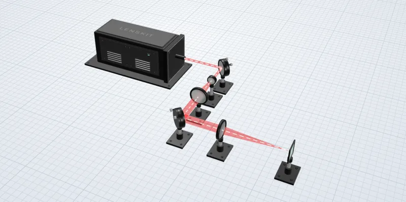
Laser beam path modeling
Lay out your laser, mirrors, and lenses, and trace the beam through them. See where it focuses and how large the spot is, including the aberrations a spot-size formula leaves out.
Free to use · Runs in your browser · No lens-design training needed

Real lenses, not ideal ones
See how spherical aberration and chromatic focus shift move a stock lens’s focus away from its rated focal length.
The whole path at once
Source, fold mirrors, beam expander, and focusing lens, traced together with the spacing you’ll build.
Parts you can order
Insert any of 2,471 supported Thorlabs singlets. Each lens keeps its part number for your order.


01 Source
Set a collimated flat-top or Gaussian beam, its diameter, and its wavelengths. This one is a 4 mm flat-top beam at 1.064 µm.
Every beam, spot, and focus position on this page is traced by the lenskit engine as you scroll. Results are for each lens’s nominal prescription and don’t include manufacturing tolerances.
Analysis
Every analysis runs on the system you built, in your browser. Start with the spot at your Image Plane, then look closer when a number surprises you.
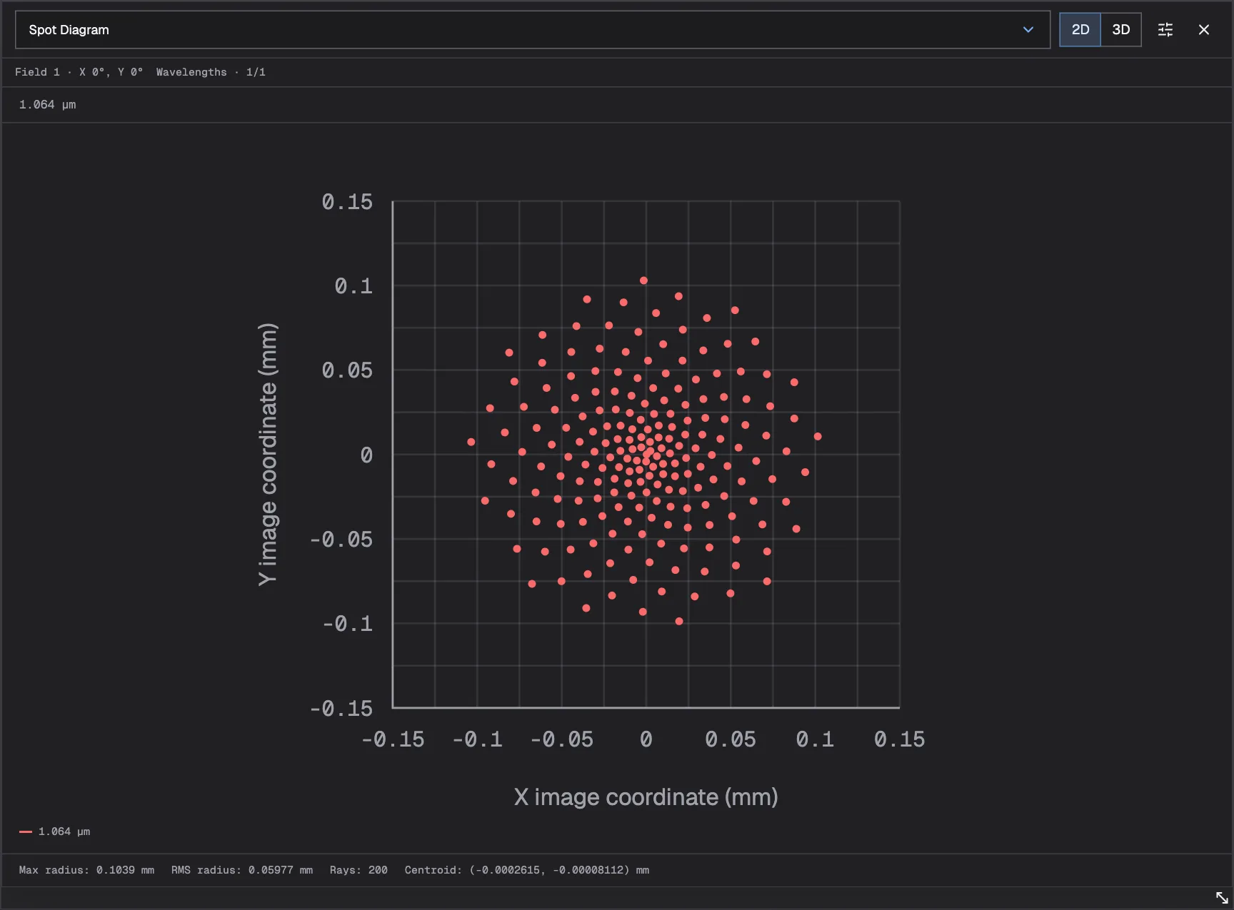
01 Spot Diagram
Where the rays land on the Image Plane, with RMS and maximum spot radius and the centroid.
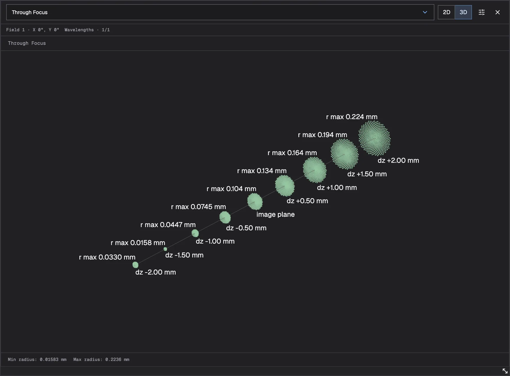
02 Through Focus
Spot size at planes before and after the Image Plane, so you can see how quickly the focus grows as the working distance changes.
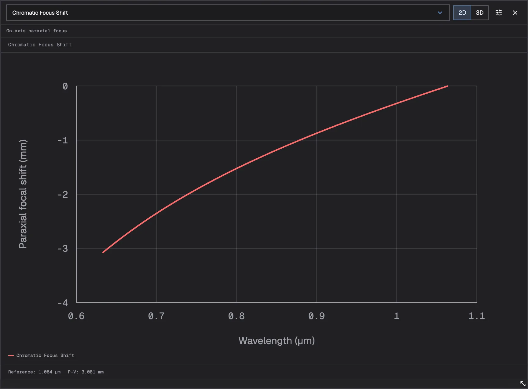
03 Chromatic Focus Shift
Paraxial focus position across the source spectrum, such as a 633 nm pointer next to a 1.064 µm process beam.
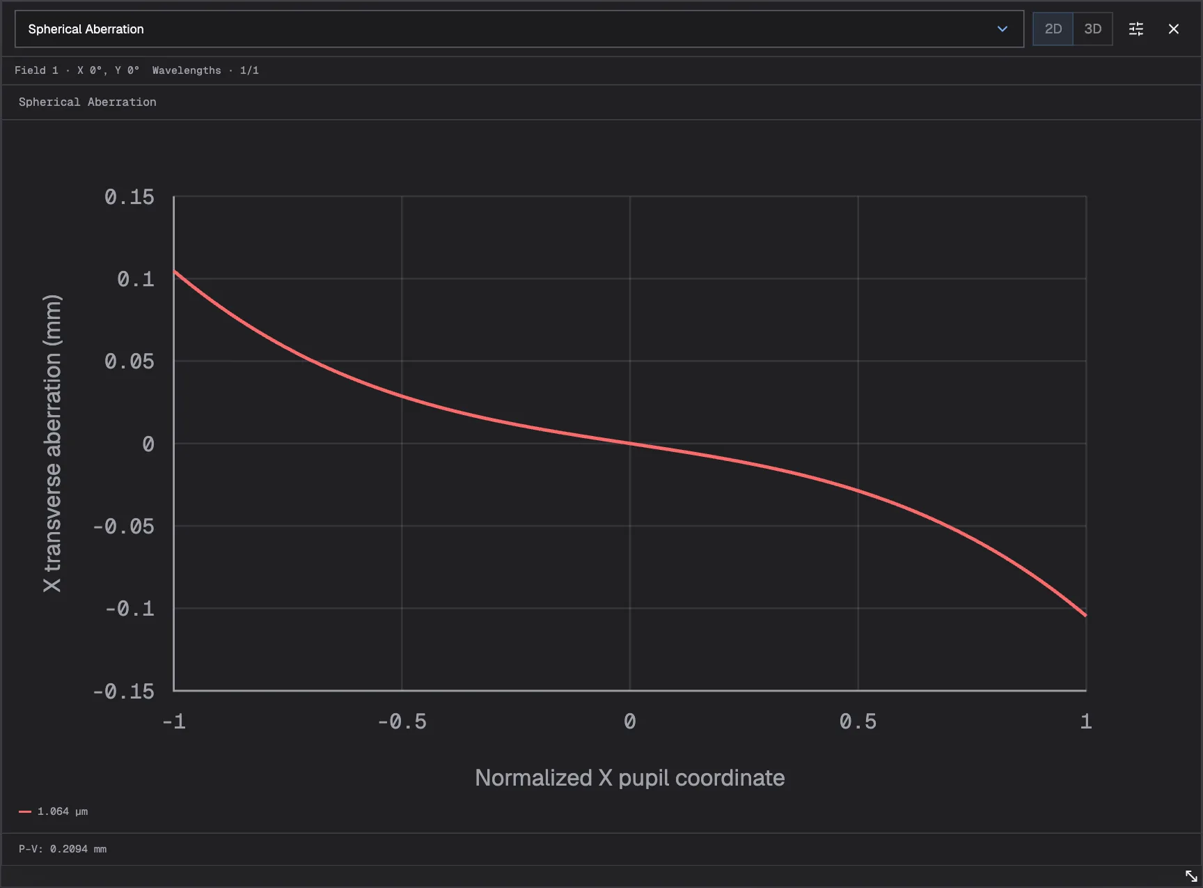
04 Spherical Aberration
How rays at the edge of the beam focus differently from rays at the center.
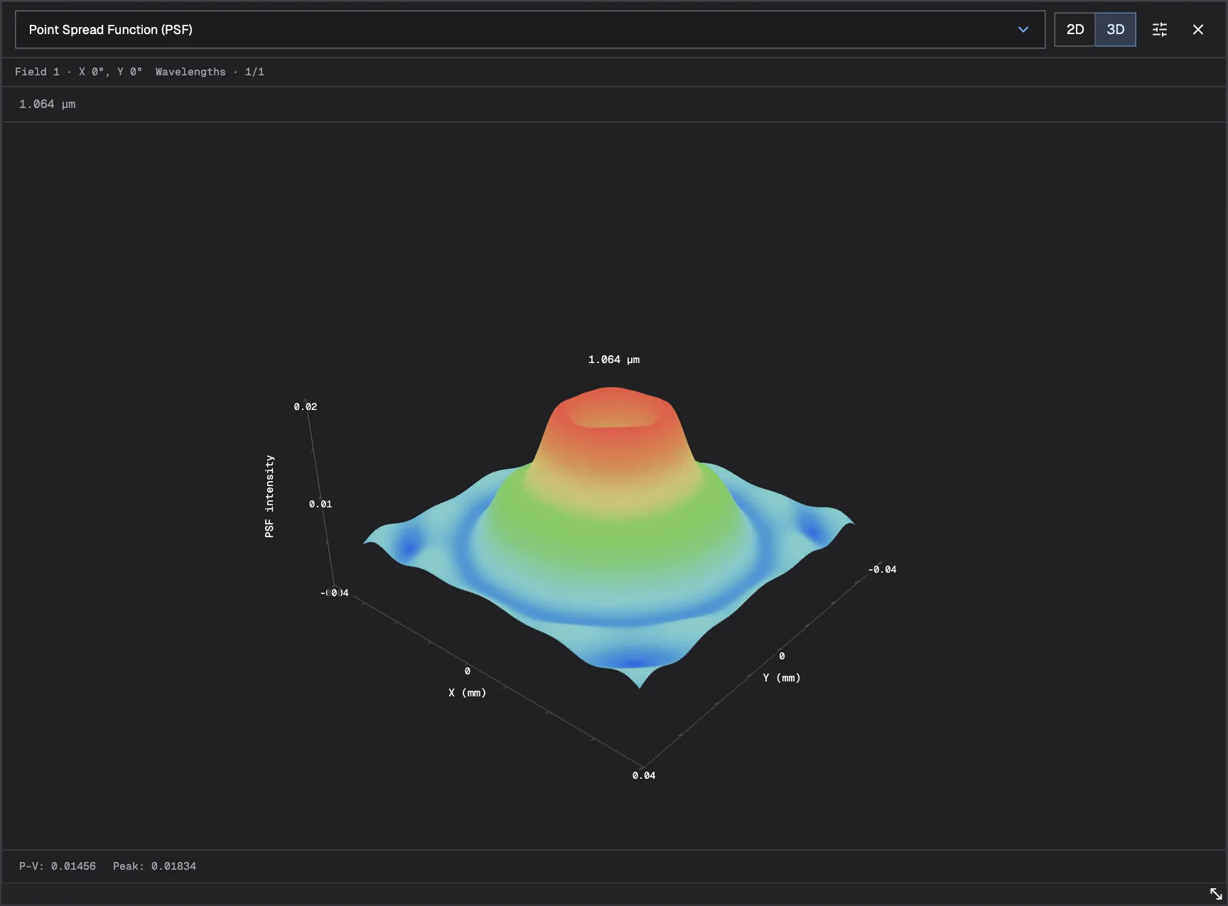
05 Point Spread Function (PSF)
The modeled intensity at the Image Plane, as a slice or a 3D surface.
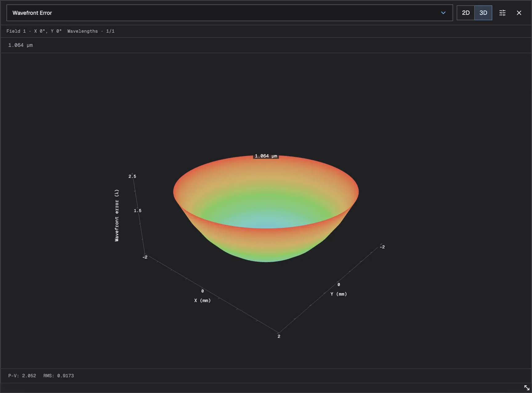
06 Wavefront Error
The optical path difference across the beam, with RMS and peak-to-valley values.
Plots show the tour's LA1509 focusing lens with the Image Plane at 100 mm and a 1.064 µm source; Chromatic Focus Shift adds a 633 nm alignment beam. Some analyses are unavailable for extended sources.
Starter systems
Open a starter close to what you’re building and inspect its layout and analyses, no account needed. Create an account to save your own copy and adapt the source, optics, and spacing.
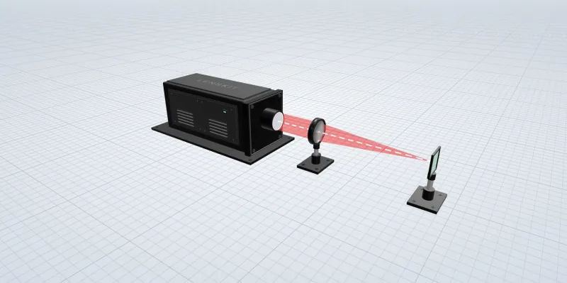
01
A collimated beam and one lens. The quickest way to see where a real lens focuses and how fast the spot grows on either side.
02
The system from the tour: a 1.064 µm beam folded twice, expanded 3×, and focused by a stock Thorlabs lens. Swap a lens and see how the spot changes.
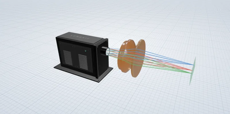
03
A multi-element scan lens for CO₂ lasers, traced at several field angles. See how the spot holds up across the scan field.
Keep the work moving
The layout, parts, and source settings stay together, so whoever opens your link sees the system you built and can run its analyses themselves.
Send an unlisted link to a colleague, customer, or supplier. They can inspect the system, run supported analyses, and save their own copy without changing yours.
New systems and copies start private. Reopen them from your account, and recover unsaved drafts if a tab closes.
Import supported OSLO .len or Zemax .zmx prescriptions, or save lenses to your personal library and reuse them in any system.
Before you get started
What you need to begin, what the results include, and where lenskit stops.
Yes, it’s free to use. Create an account, verify your email, and choose a username to start designing. Paid features may come later; their scope and pricing haven’t been decided.
No. You build the system from a source, lenses, mirrors, and an Image Plane in a visual layout, with nothing to install. You’ll still need your requirements, such as beam size, wavelength, and working distance, and the analyses use some optics vocabulary.
Lenskit traces rays through the exact prescriptions in your system, using each glass’s refractive index at your wavelengths. The results describe those nominal lenses. Manufacturing tolerances and coatings aren’t modeled, so treat a result as a design check, not a guarantee of built performance.
Yes. Search supported Thorlabs singlets and insert them into your system; each lens keeps its part number. You can also enter your own prescription or reuse a lens from your personal library. Check current specifications with the supplier before ordering.
No. New designs are private. You can keep them private, share an unlisted link, or publish them in the gallery. Anyone with access can inspect the system and run supported analyses without an account. Editing someone else’s design saves an independent copy; the original doesn’t change.
You can import supported OSLO .len and Zemax .zmx prescriptions, including air-spaced singlets and some folded mirror paths. Review the compatibility notes before importing: cemented lenses, lens tilts, and unsupported coordinate operations are not reproduced. Export to other design programs isn’t currently available.
It isn’t a full lens design suite. Whole-system optimization, tolerancing, stray light and non-sequential analysis, coating simulation, and Gaussian beam propagation aren’t available. Gaussian sources set the input beam profile, but the beam is traced with rays, not propagated as a Gaussian beam. Optimization refines one lens at a time.
Set up your source, add the optics you’re considering, and see the modeled focus before you order anything.
Free to use · Runs in your browser · No lens-design training needed

